Adding 3D parts
Adding 3D parts for each part footprint in your design is key for realistic renderings of your board and to get tight enclosing in mechanical CAD done just one or two iterations.
Copper comes with hundreds of parts for all major categories like ICs, Inductors, Connectors, Diodes and a lot more. It’s worth mentioning that the majority of parts delivered with Copper are SMD parts, although Copper certainly comes with typical through hole parts like pin strip headers and the like. The reason being that SMD parts are much less complicated in design than through hole components and they often share a simple geometry that makes them perfect for procedural parts.
In order to keep the 3D part system flexible we decided on a cloud based approach. We host all parts on our servers, and if you are searching for parts in Copper, Copper will “ask” our servers for these and will download them. This is much like Apple Music works. Music files are stored on Apples servers. Whenever you want to listen to music iTunes downloads/streams the files from the servers and play them.
This system is very flexible and enables us to upload new 3D parts on request or ourselves everyday without sending a new App version for review.
Important: It is currently not possible to add your own 3D models. There is a good reason for that. Please read our blog post for more info about this topic: Why you can’t import 3D models yourself.
Type of parts
Copper comes with two types of parts: 3D models and procedural. Procedural parts are an awesome technology. Procedural parts expose a few attributes like pin count, height and pitch and output a 3D model. Currently Copper comes with procedural parts for QFPs, SOICs and QFNs. That means that any configuration of these ICs can be generated with a few settings, or can be downloaded from our cloud service as we have already created a few standard configurations.
Inspecting Parts has some more infos on procedural parts and how to configure them.
The other type of part is a 3D model. This is as you would expect. A file is stored on our servers that contains points and faces, textures and materials that are downloaded and added to your board.
Searching and Adding 3D parts to your board
If you have read the document about adding part numbers (“real parts”) to your footprints then you know how to add 3D parts, as the user interface is much the same.

Adding 3D parts is integrated in the 3D view. At the top of the editor window click on the 3D board viewer: ![]() . This opens the 3D view that may take a few seconds to build and load.
. This opens the 3D view that may take a few seconds to build and load.
Please note that Copper generates your 3D board automatically using procedural algorithms. Copper analyses your board, creates holes for pads and vias, generates textures with traces, solder mask, and various others. Copper even generates solder joints using the cream layer as a reference.
Categories
As stated before, Copper comes with hundreds of parts. To easier find parts we have added part categories.
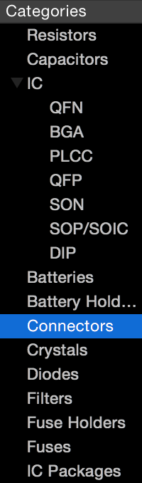
Categories help to quickly browse available parts. Just click on a category on the left side. If you did not enter search keywords, Copper will load and display all parts that it holds in that category.
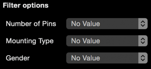
Filters
If the displayed parts have filterable attributes then the filter view will be displayed. This allows you to further remove unwanted parts from the list and allows you to find a part quickly and easily. Typical filters are package name and mounting type or if it’s a male or female connector.
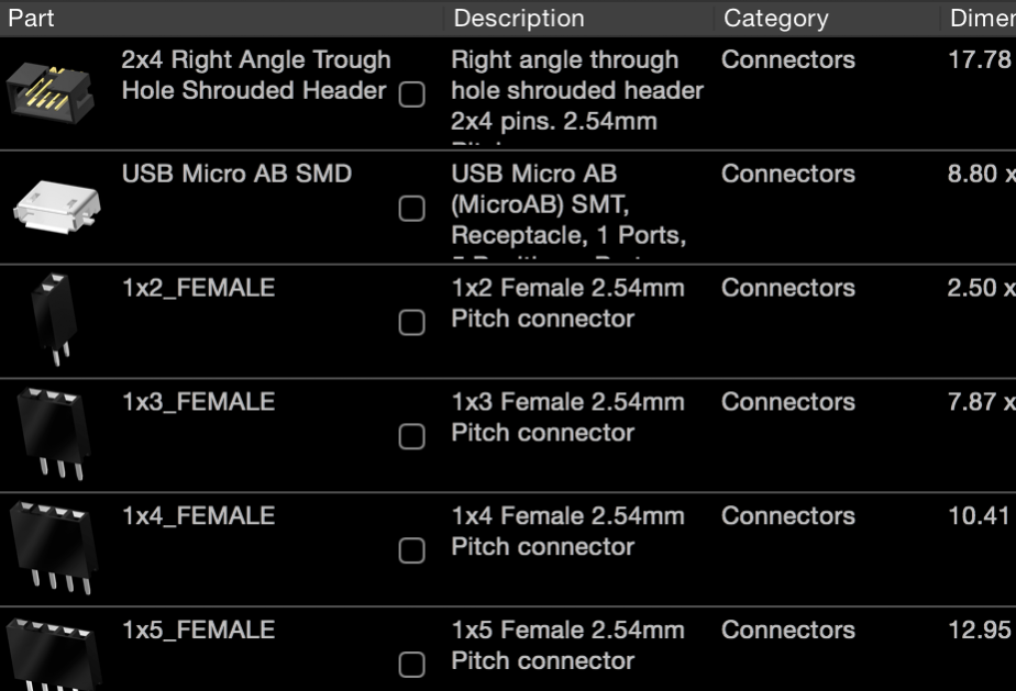
Results Browser
The results of your part query is shown in the result browser. In this list the most important information are noted for each found 3D part. You can see a small image with a perspective representation of the 3D part. Press the space key to activate Quick Look which shows the part image(s) in large and also lets you view the part from all angles.
In the table a few other information can be very helpful to decide if it’s the correct part like the dimension or height. All our parts use the metric system and evenly scaled and positioned. Use the Dimensions and Height columns to quickly determine if the part will fit your 2D footprint (Open Inspector in part mode, you will see the footprint dimensions in the Dimension Inspector section – more about the Inspector in the next section).
Double click a 3D part to attach it to the currently selected part footprint. Sometimes you will have to position the 3D part so it matches the 2D footprint. This is described in Inspecting Parts.